|
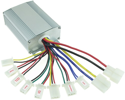
Speed Controller SPD-24500R Installation and Wiring |
|
| Rated Voltage | 24 Volts |
| Rated For Motors | Up To 500 Watts |
| Maximum Current | 30 Amps |
| Rated For Chargers | Up To 3 Amps |
| Conversion Efficiency | 95% |
| Under Voltage Protection | 20.5 Volts ± 1.0 Volt |
| Recommended Fuse Size | 40 Amps |
| Dimensions (including mounting tabs) | 4" Long x 2-5/8" Wide x 1-1/2" High |
| Labeled Connectors: The two
identical connectors with black and red wires going to them are
labeled for easy identification. Under Voltage Battery Protection:
When the battery pack falls below a specific Voltage the controller
turns the motor off preventing over discharging of the battery pack
which extends the lifespan of the battery pack. (The cutoff value is
approximately 20.5 Volts ± 1.0 Volt) |
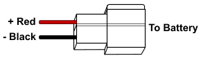
*Power Connector
Mating Connector Item # CNX-50 |
|
|
|
Motor Connector
Mating Connector Item # CNX-50 |
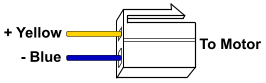 Required Connection |
|
Throttle
Connector
Mating Connector Item # CNX-52 |
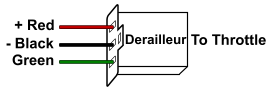 Required Connection |
|
| Key or
Power Switch Blue & Blue Disconnected = Power Off Blue & Blue Connected = Power On Mating Connector Item # CNX-51 |
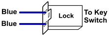 Required Connection |
|
|
Speed Selection Switch
All Wires Disconnected = High Black & Yellow Connected = Medium Black & Red Connected = Low Mating Connector Item # CNX-52 |
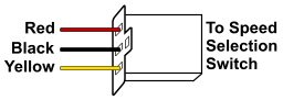 ~Optional Connection |
|
|
Reverse
Switch Connector Black & Yellow Connected = Motor Reverse Mating Connector Item # CNX-51 |
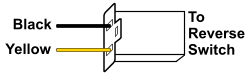 ~Optional Connection |
|
Charger Port Connector
|
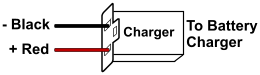 ~Optional Connection |
|
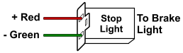
| Brake
Switch Connector Green & Black Connected = Motor Off and Brake Light On Mating Connector Item # CNX-51 |
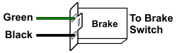 ~Optional Connection |
|
Brake
Light Connector
|
 ~Optional Connection |
|
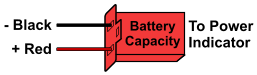
Power
Indicator Connector
|
 ~Optional Connection |
|
*The power connector
should be the last connection made. *Fuse or circuit breaker protection should be installed between speed controller and battery pack. ~Optional Connections do not need to be hooked up for the speed controller to operate. |