|
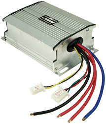
Speed Controller SPD-241000B Installation and Wiring |
|
| Rated Voltage | 24 Volts |
| Rated For Motors | Up To 1000 Watts |
| Maximum Current | 60 Amps |
| Conversion Efficiency | 95% |
| Under Voltage Protection | 20.5 Volts |
| Recommended Fuse/Circuit Breaker Size | 60 Amps |
| Throttle | Hall Effect Throttle (Standard 3 Wire) |
| Dimensions | 6" x 4" x 2" |
| Requires Heavy-Duty Switch or Power Contactor: This controller does
not have a built in power relay to turn it on and off. A heavy-duty power
disconnect switch such as
item # SWT-700
or power relay such as
item # RLY-24150
is needed to turn this controller on and off.
Under Voltage Battery Protection:
When the battery pack falls below a specific Voltage the controller turns the
motor off preventing over discharging of the battery pack which extends the
battery packs lifespan. (The cutoff value is approximately 20.5 Volts ± 1.0
Volts) |
|
*Power Connector
12 Gauge Wire |
Required Connection |
|
|
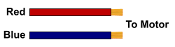
Motor Connector
12 Gauge Wire |
Required Connection |
|
Throttle Connector
|
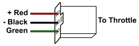 Required Connection |
|
| Brake Lever Connector
|
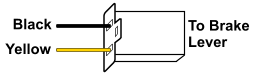 ~Optional Connection |

|
*The battery pack should be the last connection made. *A power switch, power contactor, or power relay and fuse or circuit breaker protection needs to be installed between the speed controller and the battery pack. *The two red wires going to the battery and motor are connected together inside of the controller so it does not matter which one goes to the battery or motor. ~Optional connections do not need to be connected to anything in order for the controller to operate. |